
目录
一、实验拓扑图:
编辑二、实验要求
三、实验思路
四、实验步骤
(1) eth-trunk技术配置
(2)vlan 技术配置
(3)配置SW1、SW2、AR1、ISP的IP地址
(4)在交换机SW1、SW2、SW3、SW4上面配置MSTP
(5)配置虚拟网段
(6)三层交换机开启DHCP服务使PC获得IP地址
PC开启DHCP服务:
(7)内网使用路由协议(ospf)使内网全通
(8)全网通测试
一、实验拓扑图:
-
 二、实验要求
1、内网IP地址使用172.16.0.0/16
2、SW1和sw2之间互为备份;
3、VRRP/stp/vlan/eth-trunk均使用;
4、所有pc均通过DHCP获取IP地址;
5、ISP只配置IP地址;
6、所有电脑可以正常访问ISP路由器环回
三、实验思路
- 首先我们是要在交换机上面进行配置,然后才是路由器的配置(明确配置设备的顺序)
- 在交换机上面要进行VRRP/stp/vlan/eth-trunk这么多技术的配置要有先后顺序:(这是我选择的顺序)eth-trunk > vlan > stp > vrrp以上顺序是根据网络分层模型从底层到高层的逻辑进行的,同时也考虑到了实际网络中的稳定性和可用性需求。在实际实验操作中,可能需要根据具体的网络环境和实验目的进行适当的调整。
- 然后给设备配置IP地址(PC使用DHCP协议获取)
- 搞通私网、公网
- 最后实现全网达
四、实验步骤
交换机SW1、SW2、SW3、SW4 和 路由器AR1、ISP的配置
(1) eth-trunk技术配置
[SW1]int Eth-Trunk 0[SW1-Eth-Trunk0]trunkport GigabitEthernet 0/0/1 to 0/0/2[SW2]int Eth-Trunk 0[SW2-Eth-Trunk0]trunkport GigabitEthernet 0/0/1 to 0/0/2(2)vlan 技术配置
SW3:
[SW3]int g0/0/1[SW3-GigabitEthernet0/0/1]port link-type access[SW3-GigabitEthernet0/0/1]port default vlan 2[SW3-GigabitEthernet0/0/1]int g0/0/1[SW3-GigabitEthernet0/0/1]int g0/0/2[SW3-GigabitEthernet0/0/2]port link-type access[SW3-GigabitEthernet0/0/2]port default vlan 3[SW3-GigabitEthernet0/0/2]int g0/0/3[SW3-GigabitEthernet0/0/3]port link-type trunk[SW3-GigabitEthernet0/0/3]port trunk allow-pass vlan 2 3[SW3-GigabitEthernet0/0/3]int g0/0/4[SW3-GigabitEthernet0/0/4]port link-type trunk[SW3-GigabitEthernet0/0/4]port trunk allow-pass vlan 2 3[SW3-GigabitEthernet0/0/4]SW4:
[SW4]vlan batch 2 3[SW4]int g0/0/1[SW4-GigabitEthernet0/0/1]p l a[SW4-GigabitEthernet0/0/1]port default vlan 2[SW4-GigabitEthernet0/0/1]int g0/0/2[SW4-GigabitEthernet0/0/2]p l a[SW4-GigabitEthernet0/0/2]port default vlan 3[SW4-GigabitEthernet0/0/2]int g0/0/3[SW4-GigabitEthernet0/0/3]p l t[SW4-GigabitEthernet0/0/3]port trunk allow-pass vlan 2 3[SW4-GigabitEthernet0/0/3]int g0/0/4[SW4-GigabitEthernet0/0/4]p l t[SW4-GigabitEthernet0/0/4]port trunk allow-pass vlan 2 3[SW4-GigabitEthernet0/0/4]SW1:
[SW1]vlan batch 2 3 10 20[SW1]int Eth-Trunk 0[SW1-Eth-Trunk0]trunkport GigabitEthernet 0/0/1 to 0/0/2[SW1-Eth-Trunk0]p l t[SW1-Eth-Trunk0]port trunk allow-pass vlan 2 3[SW1-Eth-Trunk0]q[SW1]int g0/0/3[SW1-GigabitEthernet0/0/3]p l t[SW1-GigabitEthernet0/0/3]port trunk allow-pass vlan 2 3[SW1-GigabitEthernet0/0/3]int g0/0/4[SW1-GigabitEthernet0/0/4]p l t[SW1-GigabitEthernet0/0/4]port trunk allow-pass vlan 2 3[SW1-GigabitEthernet0/0/4]int g0/0/5[SW1-GigabitEthernet0/0/5]p l a[SW1-GigabitEthernet0/0/5]port default vlan 10[SW1-GigabitEthernet0/0/5]SW2:
[SW2]vlan batch 2 3 10 20[SW2]int Eth-Trunk 0[SW2-Eth-Trunk0]trunkport GigabitEthernet 0/0/1 to 0/0/2[SW2-Eth-Trunk0]p l t[SW2-Eth-Trunk0]port trunk allow-pass vlan 2 3[SW2-Eth-Trunk0]int g0/0/3[SW2-GigabitEthernet0/0/3]p l t[SW2-GigabitEthernet0/0/3]port trunk allow-pass vlan 2 3[SW2-GigabitEthernet0/0/3]int g0/0/4[SW2-GigabitEthernet0/0/4]p l t[SW2-GigabitEthernet0/0/4]port trunk allow-pass vlan 2 3[SW2-GigabitEthernet0/0/4]int g0/0/5[SW2-GigabitEthernet0/0/5]p l a[SW2-GigabitEthernet0/0/5]port default vlan 20[SW2-GigabitEthernet0/0/5](3)配置SW1、SW2、AR1、ISP的IP地址
SW1:
[SW1]int Vlanif 2[SW1-Vlanif2]ip add 172.16.0.1 26[SW1-Vlanif2]q[SW1]int Vlanif 3[SW1-Vlanif3]ip add 172.16.0.65 26[SW1]int Vlanif 10[SW1-Vlanif10]ip add 172.16.0.129 26[SW1-Vlanif10]q[SW1]dis ip int briSW2:
[SW2]int Vlanif 2[SW2-Vlanif2]ip add 172.16.0.2 26[SW2-Vlanif2]q[SW2]int Vlanif 3[SW2-Vlanif3]ip add 172.16.0.66 26[SW2-Vlanif3]q[SW2]int Vlanif 20[SW2-Vlanif20]ip add 172.16.0.193 26[SW2-Vlanif20]q[SW2]dis ip int briR1:
[R1]int g0/0/1[R1-GigabitEthernet0/0/1]ip add 172.16.0.130 26[R1-GigabitEthernet0/0/1]int g0/0/2[R1-GigabitEthernet0/0/2]ip add 172.16.0.194 26[R1-GigabitEthernet0/0/2]q[R1]int g0/0/0[R1-GigabitEthernet0/0/0]ip add 12.0.0.1 24[R1]dis ip int briISP:
[ISP]int g0/0/0[ISP-GigabitEthernet0/0/0]ip add 12.0.0.2 24[ISP-GigabitEthernet0/0/0]int l0[ISP-LoopBack0]ip add 2.2.2.2 24[ISP-LoopBack0]q[ISP]dis ip int bri(4)在交换机SW1、SW2、SW3、SW4上面配置MSTP
SW1:
[SW1]stp enable[SW1]stp mode mstp[SW1]stp region-configuration[SW1-mst-region]region-name gxc1[SW1-mst-region]instance 1 vlan 2[SW1-mst-region]instance 2 vlan 3[SW1-mst-region]active region-configuration #激活区域配置模式[SW1-mst-region]q[SW1]stp instance 1 root primary[SW1]stp instance 2 root secondarySW2:
[SW2]stp enable[SW2]stp mode mstp[SW2]stp region-configuration[SW2-mst-region]region-name gxc1[SW2-mst-region]instance 1 vlan 2[SW2-mst-region]instance 2 vlan 3[SW2-mst-region]active region-configuration[SW2-mst-region]q[SW2]stp instance 1 root secondary[SW2]stp instance 2 root primarySW3:
[SW3]stp enable[SW3]stp mode mstp[SW3]stp region-configuration[SW3-mst-region]region-name gxc1[SW3-mst-region]instance 1 vlan 2[SW3-mst-region]instance 2 vlan 3[SW3-mst-region]active region-configuration[SW3-mst-region]q[SW3]port-group group-member GigabitEthernet 0/0/1 to g0/0/2[SW3-port-group]stp edged-port enable #设置STP边缘端口,不再参与STP选举[SW3]stp bpdu-protection #设置STP BPDU保护SW4:
[SW4]stp enable[SW4]stp mode mstp[SW4]stp region-configuration[SW4-mst-region]region-name gxc1[SW4-mst-region]instance 1 vlan 2[SW4-mst-region]instance 2 vlan 3[SW4-mst-region]active region-configuration[SW4-mst-region]q[SW4]port-group group-member GigabitEthernet 0/0/1 to g0/0/2[SW4-port-group]stp edged-port enable[SW4]stp bpdu-protection(5)配置虚拟网段
SW1:
[SW1]int Vlanif 2[SW1-Vlanif2]vrrp vrid 1 virtual-ip 172.16.0.62[SW1-Vlanif2]vrrp vrid 1 priority 120[SW1-Vlanif2]vrrp vrid 1 track interface g0/0/5 #跟踪相应的接口[SW1-Vlanif2]vrrp vrid 1 track interface g0/0/5 reduced 30 #减小接口对应的优先级[SW1-Vlanif2]q[SW1]int Vlanif 3[SW1-Vlanif3]vrrp vrid 2 virtual-ip 172.16.0.126SW2:
[SW2-Vlanif2]vrrp vrid 1 virtual-ip 172.16.0.62[SW2-Vlanif2]q[SW2]int Vlanif 3[SW2-Vlanif3]vrrp vrid 2 virtual-ip 172.16.0.126[SW2-Vlanif3]vrrp vrid 2 priority 120[SW2-Vlanif3]vrrp vrid 2 track interface Vlanif 20[SW2-Vlanif3]vrrp vrid 2 track interface Vlanif 20 reduced 30(6)三层交换机开启DHCP服务使PC获得IP地址
SW1:
[SW1]DHCP enable[SW1]ip pool aa[SW1-ip-pool-aa]network 172.16.0.0 mask 26[SW1-ip-pool-aa]gateway-list 172.16.0.62[SW1-ip-pool-aa]dns-list 8.8.8.8[SW1-ip-pool-aa]q[SW1]int Vlanif 2[SW1-Vlanif2]dhcp select global[SW1-Vlanif2]q[SW1]ip pool bb[SW1-ip-pool-bb]network 172.16.0.64 mask 26[SW1-ip-pool-bb]gateway-list 172.16.0.126[SW1-ip-pool-bb]dns-list 8.8.8.8[SW1-ip-pool-bb]q[SW1]int Vlanif 3[SW1-Vlanif3]dhcp select global[SW1-Vlanif3]q[SW1]SW2:
[SW2]dhcp enable[SW2]ip pool aa[SW2-ip-pool-aa]network 172.16.0.0 mask 26[SW2-ip-pool-aa]gateway-list 172.16.0.62[SW2-ip-pool-aa]dns-list 8.8.8.8[SW2-ip-pool-aa]q[SW2]int Vlanif 2[SW2-Vlanif2]dhcp select global[SW2-Vlanif2]q[SW2]ip pool bb[SW2-ip-pool-bb]network 172.16.0.64 mask 26[SW2-ip-pool-bb]gateway-list 172.16.0.126[SW2-ip-pool-bb]dns-list 8.8.8.8[SW2-ip-pool-bb]q[SW2]int Vlanif 3[SW2-Vlanif3]dhcp select global[SW2-Vlanif3]qPC开启DHCP服务:
PC1:

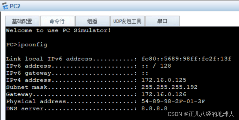
PC2:
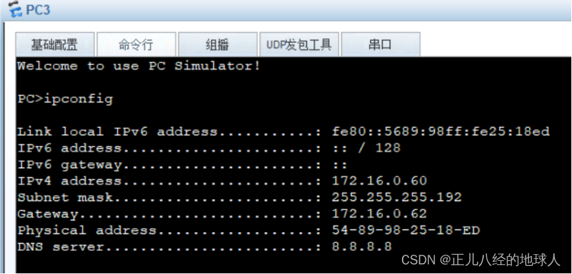
PC3:
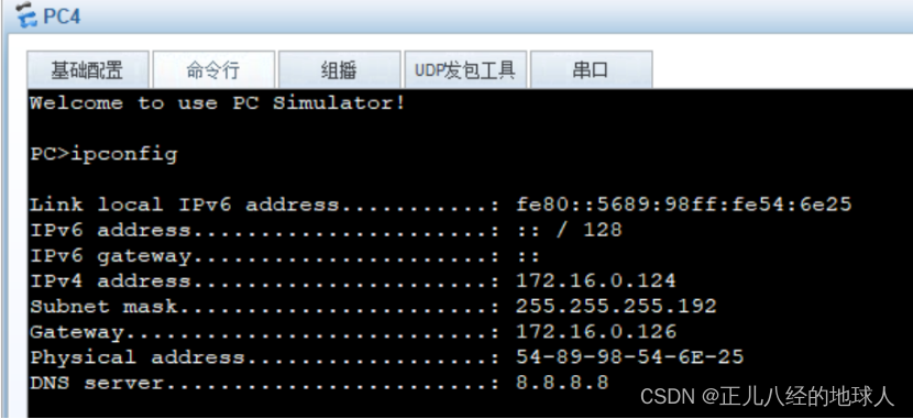
PC4:
(7)内网使用路由协议(ospf)使内网全通
R1:
[R1]ospf 1 router-id 1.1.1.1[R1-ospf-1]a 0[R1-ospf-1-area-0.0.0.0]network 172.16.0.128 0.0.0.63[R1-ospf-1-area-0.0.0.0]network 172.16.0.192 0.0.0.63[R1-ospf-1-area-0.0.0.0]q[R1]dis ospf peer bri 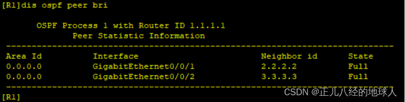
[R1]ip route-static 0.0.0.0 0 12.0.0.2[R1]acl 2000[R1-acl-basic-2000]rule permit source 172.16.0.0 0.0.0.255[R1-acl-basic-2000]q[R1]int g0/0/0[R1-GigabitEthernet0/0/0]nat outbound 2000[R1-GigabitEthernet0/0/0]q[R1]ospf 1[R1-ospf-1]default-route-advertise[R1-ospf-1]qSW1:
[SW1]ospf 1 router-id 2.2.2.2[SW1-ospf-1]a 0[SW1-ospf-1-area-0.0.0.0]network 172.16.0.128 0.0.0.63[SW1-ospf-1-area-0.0.0.0]network 172.16.0.0 0.0.0.63[SW1-ospf-1-area-0.0.0.0]network 172.16.0.64 0.0.0.63[SW1-ospf-1-area-0.0.0.0]q[SW1-ospf-1]q[SW1]dis ospf peer bri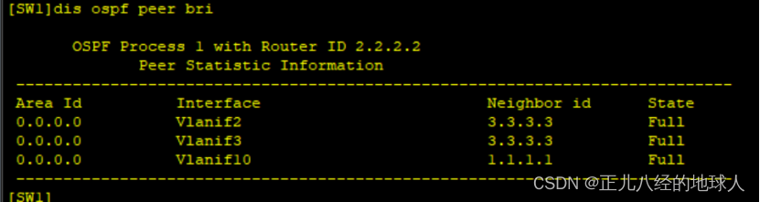
SW2:
[SW2]ospf 1 router-id 3.3.3.3[SW2-ospf-1]a 0[SW2-ospf-1-area-0.0.0.0]network 172.16.0.192 0.0.0.63[SW2-ospf-1-area-0.0.0.0]network 172.16.0.0 0.0.0.63[SW2-ospf-1-area-0.0.0.0]network 172.16.0.64 0.0.0.63[SW2-ospf-1-area-0.0.0.0]q[SW2-ospf-1]q[SW2]dis ospf peer bri 
(8)全网通测试
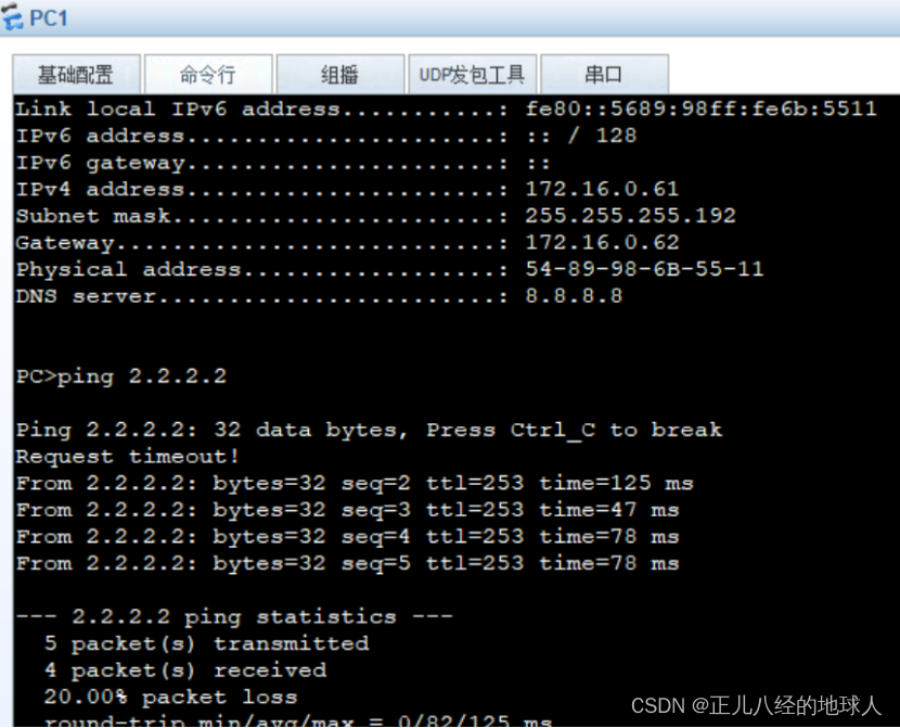
PC1 ping ISP 环回地址
PC3 ping ISP环回地址

测试通过!!!
如果想要观察VRRP备份链路情况,可以断掉SW1或SW2与R1相连的链路,自行观察三层交换机的vrrp表中的主备关系的转换。
至此本实验全部完成!!!


记住我及首页定制 "进阶SpringBoot之 SpringSecurity(4)记住我及首页定制")
