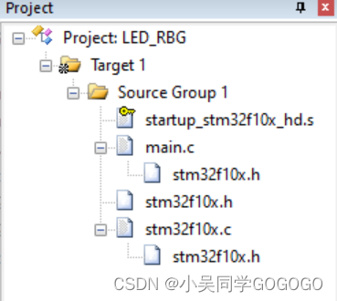
项目结构
stm32f10x.h 文件
//寄存器的值常常是芯片外设自动更改的,即使CPU没有执行程序,也有可能发生变化
//编译器有可能会对没有执行程序的变量进行优化//volatile表示易变的变量,防止编译器优化,
#define     __IO    volatile
typedef unsigned int uint32_t;
typedef unsigned short uint16_t;// GPIO 寄存器结构体定义
typedef struct
{__IO uint32_t CRL;       // 端口配置低寄存器,     地址偏移0X00__IO uint32_t CRH;       // 端口配置高寄存器,     地址偏移0X04__IO uint32_t IDR;       // 端口数据输入寄存器,   地址偏移0X08__IO uint32_t ODR;       // 端口数据输出寄存器,   地址偏移0X0C__IO uint32_t BSRR;      // 端口位设置/清除寄存器,地址偏移0X10__IO uint32_t BRR;       // 端口位清除寄存器,     地址偏移0X14__IO uint32_t LCKR;      // 端口配置锁定寄存器,   地址偏移0X18
} GPIO_TypeDef;/*片上外设基地址  */
#define PERIPH_BASE           ((unsigned int)0x40000000)/*APB2 总线基地址 */
#define APB2PERIPH_BASE       (PERIPH_BASE + 0x10000)
/* AHB总线基地址 */
#define AHBPERIPH_BASE        (PERIPH_BASE + 0x20000)/*GPIO外设基地址*/
#define GPIOA_BASE            (APB2PERIPH_BASE + 0x0800)
#define GPIOB_BASE            (APB2PERIPH_BASE + 0x0C00)
#define GPIOC_BASE            (APB2PERIPH_BASE + 0x1000)
#define GPIOD_BASE            (APB2PERIPH_BASE + 0x1400)
#define GPIOE_BASE            (APB2PERIPH_BASE + 0x1800)
#define GPIOF_BASE            (APB2PERIPH_BASE + 0x1C00)
#define GPIOG_BASE            (APB2PERIPH_BASE + 0x2000)/*RCC外设基地址*/
#define RCC_BASE      (AHBPERIPH_BASE + 0x1000)// GPIO 外设声明
#define GPIOA               ((GPIO_TypeDef *) GPIOA_BASE)
#define GPIOB               ((GPIO_TypeDef *) GPIOB_BASE)
#define GPIOC               ((GPIO_TypeDef *) GPIOC_BASE)
#define GPIOD               ((GPIO_TypeDef *) GPIOD_BASE)
#define GPIOE               ((GPIO_TypeDef *) GPIOE_BASE)
#define GPIOF               ((GPIO_TypeDef *) GPIOF_BASE)
#define GPIOG               ((GPIO_TypeDef *) GPIOG_BASE)// RCC 外设声明
#define RCC                 ((RCC_TypeDef *) RCC_BASE)/*RCC的AHB1时钟使能寄存器地址,强制转换成指针*/
#define RCC_APB2ENR      *(unsigned int*)(RCC_BASE+0x18)/*GPIO引脚号定义*/
#define GPIO_Pin_0              ((uint16_t)0x0001)  /*!< 选择Pin0 (1<<0) */
#define GPIO_Pin_1              ((uint16_t)0x0002)  /*!< 选择Pin1 (1<<1)*/
#define GPIO_Pin_2              ((uint16_t)0x0004)  /*!< 选择Pin2 (1<<2)*/
#define GPIO_Pin_3              ((uint16_t)0x0008)  /*!< 选择Pin3 (1<<3)*/
#define GPIO_Pin_4              ((uint16_t)0x0010)  /*!< 选择Pin4 */
#define GPIO_Pin_5              ((uint16_t)0x0020)  /*!< 选择Pin5 */
#define GPIO_Pin_6              ((uint16_t)0x0040)  /*!< 选择Pin6 */
#define GPIO_Pin_7              ((uint16_t)0x0080)  /*!< 选择Pin7 */
#define GPIO_Pin_8              ((uint16_t)0x0100)  /*!< 选择Pin8 */
#define GPIO_Pin_9              ((uint16_t)0x0200)  /*!< 选择Pin9 */
#define GPIO_Pin_10             ((uint16_t)0x0400)  /*!< 选择Pin10 */
#define GPIO_Pin_11             ((uint16_t)0x0800)  /*!< 选择Pin11 */
#define GPIO_Pin_12             ((uint16_t)0x1000)  /*!< 选择Pin12 */
#define GPIO_Pin_13             ((uint16_t)0x2000)  /*!< 选择Pin13 */
#define GPIO_Pin_14             ((uint16_t)0x4000)  /*!< 选择Pin14 */
#define GPIO_Pin_15             ((uint16_t)0x8000)  /*!< 选择Pin15 */
#define GPIO_Pin_All            ((uint16_t)0xFFFF)  /*!< 选择全部引脚 *//**
* GPIO输出速率枚举定义
*/
typedef enum
{GPIO_Speed_10MHz = 1,         // 10MHZ        (01)bGPIO_Speed_2MHz,              // 2MHZ         (10)bGPIO_Speed_50MHz              // 50MHZ        (11)b
} GPIOSpeed_TypeDef;/**
* GPIO工作模式枚举定义
*/
typedef enum
{GPIO_Mode_AIN = 0x0,           // 模拟输入     (0000 0000)bGPIO_Mode_IN_FLOATING = 0x04,  // 浮空输入     (0000 0100)bGPIO_Mode_IPD = 0x28,          // 下拉输入     (0010 1000)bGPIO_Mode_IPU = 0x48,          // 上拉输入     (0100 1000)bGPIO_Mode_Out_OD = 0x14,       // 开漏输出     (0001 0100)bGPIO_Mode_Out_PP = 0x10,       // 推挽输出     (0001 0000)bGPIO_Mode_AF_OD = 0x1C,        // 复用开漏输出  (0001 1100)bGPIO_Mode_AF_PP = 0x18         // 复用推挽输出  (0001 1000)b
} GPIOMode_TypeDef;/**
* GPIO初始化结构体类型定义
*/
typedef struct
{uint16_t GPIO_Pin;             /*!< 选择要配置的GPIO引脚可输入 GPIO_Pin_ 定义的宏 */GPIOSpeed_TypeDef GPIO_Speed;  /*!< 选择GPIO引脚的速率可输入 GPIOSpeed_TypeDef 定义的枚举值 */GPIOMode_TypeDef GPIO_Mode;    /*!< 选择GPIO引脚的工作模式可输入 GPIOMode_TypeDef 定义的枚举值 */
} GPIO_InitTypeDef;void GPIO_ResetBits(GPIO_TypeDef* GPIOx, uint16_t GPIO_Pin);void GPIO_SetBits(GPIO_TypeDef* GPIOx, uint16_t GPIO_Pin);void GPIO_Init(GPIO_TypeDef* GPIOx, GPIO_InitTypeDef* GPIO_InitStruct);
stm32f10x.c 文件
#include "stm32f10x.h"/**
*函数功能:设置引脚为低电平
*参数说明:GPIOx:该参数为GPIO_TypeDef类型的指针,指向GPIO端口的地址
*        GPIO_Pin:选择要设置的GPIO端口引脚,可输入宏GPIO_Pin_0-15,
*                 表示GPIOx端口的0-15号引脚。
*/void GPIO_ResetBits(GPIO_TypeDef* GPIOx, uint16_t GPIO_Pin)
{/*设置GPIOx端口BRR寄存器的第GPIO_Pin位,使其输出低电平*//*因为BRR寄存器写0不影响,宏GPIO_Pin只是对应位为1,其它位均为0,所以可以直接赋值*/GPIOx->BRR = GPIO_Pin;
}/**
*函数功能:设置引脚为高电平
*参数说明:GPIOx:该参数为GPIO_TypeDef类型的指针,指向GPIO端口的地址
*        GPIO_Pin:选择要设置的GPIO端口引脚,可输入宏GPIO_Pin_0-15,
*                 表示GPIOx端口的0-15号引脚。
*/
void GPIO_SetBits(GPIO_TypeDef* GPIOx, uint16_t GPIO_Pin)
{/*设置GPIOx端口BSRR寄存器的第GPIO_Pin位,使其输出高电平*//*因为BSRR寄存器写0不影响,宏GPIO_Pin只是对应位为1,其它位均为0,所以可以直接赋值*/GPIOx->BSRR = GPIO_Pin;
}/**
*函数功能:初始化引脚模式
*参数说明:GPIOx,该参数为GPIO_TypeDef类型的指针,指向GPIO端口的地址
*         GPIO_InitTypeDef:GPIO_InitTypeDef结构体指针,指向初始化变量
*/
void GPIO_Init(GPIO_TypeDef* GPIOx, GPIO_InitTypeDef* GPIO_InitStruct)
{uint32_t currentmode =0x00,currentpin = 0x00,pinpos = 0x00,pos = 0x00;uint32_t tmpreg = 0x00, pinmask = 0x00;/*---------------- GPIO 模式配置 -------------------*/// 把输入参数GPIO_Mode的低四位暂存在currentmodecurrentmode = ((uint32_t)GPIO_InitStruct->GPIO_Mode) &((uint32_t)0x0F);// bit4是1表示输出,bit4是0则是输入// 判断bit4是1还是0,即首选判断是输入还是输出模式if ((((uint32_t)GPIO_InitStruct->GPIO_Mode) &((uint32_t)0x10)) != 0x00){// 输出模式则要设置输出速度currentmode |= (uint32_t)GPIO_InitStruct->GPIO_Speed;}/*-----GPIO CRL 寄存器配置 CRL寄存器控制着低8位IO- ----*/// 配置端口低8位,即Pin0~Pin7if (((uint32_t)GPIO_InitStruct->GPIO_Pin &((uint32_t)0x00FF)) != 0x00){// 先备份CRL寄存器的值tmpreg = GPIOx->CRL;// 循环,从Pin0开始配对,找出具体的Pinfor (pinpos = 0x00; pinpos < 0x08; pinpos++){// pos的值为1左移pinpos位pos = ((uint32_t)0x01) << pinpos;// 令pos与输入参数GPIO_PIN作位与运算currentpin = (GPIO_InitStruct->GPIO_Pin) & pos;//若currentpin=pos,则找到使用的引脚if (currentpin == pos){//pinpos的值左移两位(乘以4),因为寄存器中4个位配置一个引脚pos = pinpos << 2;//把控制这个引脚的4个寄存器位清零,其它寄存器位不变pinmask = ((uint32_t)0x0F) << pos;tmpreg &= ~pinmask;// 向寄存器写入将要配置的引脚的模式tmpreg |= (currentmode << pos);// 判断是否为下拉输入模式if (GPIO_InitStruct->GPIO_Mode == GPIO_Mode_IPD){// 下拉输入模式,引脚默认置0,对BRR寄存器写1对引脚置0GPIOx->BRR = (((uint32_t)0x01) << pinpos);}else{// 判断是否为上拉输入模式if (GPIO_InitStruct->GPIO_Mode == GPIO_Mode_IPU){// 上拉输入模式,引脚默认值为1,对BSRR寄存器写1对引脚置1GPIOx->BSRR = (((uint32_t)0x01) << pinpos);}}}}// 把前面处理后的暂存值写入到CRL寄存器之中GPIOx->CRL = tmpreg;}/*--------GPIO CRH 寄存器配置 CRH寄存器控制着高8位IO- -----*/// 配置端口高8位,即Pin8~Pin15if (GPIO_InitStruct->GPIO_Pin > 0x00FF){// // 先备份CRH寄存器的值tmpreg = GPIOx->CRH;// 循环,从Pin8开始配对,找出具体的Pinfor (pinpos = 0x00; pinpos < 0x08; pinpos++){pos = (((uint32_t)0x01) << (pinpos + 0x08));// pos与输入参数GPIO_PIN作位与运算currentpin = ((GPIO_InitStruct->GPIO_Pin) & pos);//若currentpin=pos,则找到使用的引脚if (currentpin == pos){//pinpos的值左移两位(乘以4),因为寄存器中4个位配置一个引脚pos = pinpos << 2;//把控制这个引脚的4个寄存器位清零,其它寄存器位不变pinmask = ((uint32_t)0x0F) << pos;tmpreg &= ~pinmask;// 向寄存器写入将要配置的引脚的模式tmpreg |= (currentmode << pos);// 判断是否为下拉输入模式if (GPIO_InitStruct->GPIO_Mode == GPIO_Mode_IPD){// 下拉输入模式,引脚默认置0,对BRR寄存器写1可对引脚置0GPIOx->BRR = (((uint32_t)0x01) << (pinpos + 0x08));}// 判断是否为上拉输入模式if (GPIO_InitStruct->GPIO_Mode == GPIO_Mode_IPU){// 上拉输入模式,引脚默认值为1,对BSRR寄存器写1可对引脚置1GPIOx->BSRR = (((uint32_t)0x01) << (pinpos + 0x08));}}}// 把前面处理后的暂存值写入到CRH寄存器之中GPIOx->CRH = tmpreg;}
}
main.c 文件
#ifndef STM32F10X // 防止重复引入报错
#define STM32F10X
#endif #include "stm32f10x.h"// 函数为空,目的是为了骗过编译器不报错
void SystemInit(void)
{
}void Delay(__IO uint32_t nCount)     //简单的延时函数
{for (; nCount != 0; nCount--);
}// 使用固件库点亮LED
int main(void)
{// 定义一个GPIO_InitTypeDef类型的结构体GPIO_InitTypeDef GPIO_InitStructure;// 开启GPIO端口时钟RCC_APB2ENR |= (1<<3);// 选择要控制的GPIO引脚GPIO_InitStructure.GPIO_Pin = GPIO_Pin_0;// 设置引脚模式为通用推挽输出GPIO_InitStructure.GPIO_Mode = GPIO_Mode_Out_PP;// 设置引脚速率为50MHzGPIO_InitStructure.GPIO_Speed = GPIO_Speed_50MHz;// 调用库函数,初始化GPIO引脚GPIO_Init(GPIOB, &GPIO_InitStructure);// ======PB0口闪烁======// 使引脚输出低电平,点亮LED1GPIO_ResetBits(GPIOB,GPIO_Pin_0);while (1){// 使引脚输出低电平,点亮LEDGPIO_ResetBits(GPIOB,GPIO_Pin_0);/*延时一段时间*/Delay(0xFFFF);/*使引脚输出高电平,关闭LED1*/GPIO_SetBits(GPIOB,GPIO_Pin_0);/*延时一段时间*/Delay(0xFFFF);}
}
LED灯一头接入PB0,一头接入GND,收录之后,即可实现闪烁效果。