
文章目录
- 1.安装
- 1.1.下载coin3d
- 1.2.下载quarter
- 1.3.解压并合并
- 2.在Qt中使用
- 3.画个网格
- 4.加载wrl模型
- 5.画个锤子并旋转
- 6.加载自定义视口文件
1.安装
1.1.下载coin3d
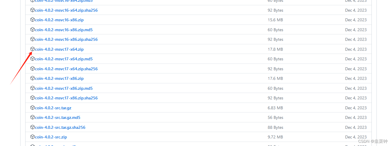
首先,到官网下载[coin3d/coin]
我是Qt5.15.2+vs2019的,因此我选择这个coin-4.0.2-msvc17-x64.zip
1.2.下载quarter
到官网下载Coin3D在Qt中的封装库【quarter】
我是Qt5.15.2+vs2019的,因此我选择这个quarter-1.2.1-Qt5.15-msvc17-x64.zip

1.3.解压并合并
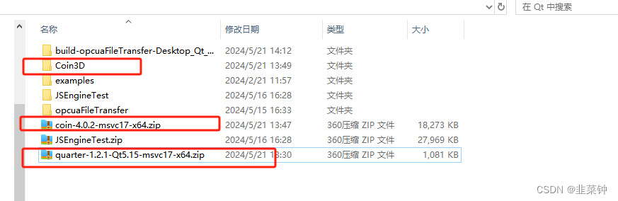
将这两个压缩包放在在同一个文件夹中,先解压coin-4.0.2-msvc17-x64.zip,然后再解压
quarter-1.2.1-Qt5.15-msvc17-x64.zip,此时,我们利用Qt编程所需要的东西全在Coin3D这个文件夹里面了:
2.在Qt中使用
在Qt工程的pro文件中添加以下语句,路径要根据你的实际路径进行更改
QT += openglINCLUDEPATH += C:\Users\Administrator\Desktop\plc\Qt\Coin3D\include
LIBS += -LC:\Users\Administrator\Desktop\plc\Qt\Coin3D\lib \
-lQuarter1
LIBS += -LC:\Users\Administrator\Desktop\plc\Qt\Coin3D\binDEFINES += QUARTER_DLL
程序的话,可以参考以下这个【a small, completely stand-alone usage example】
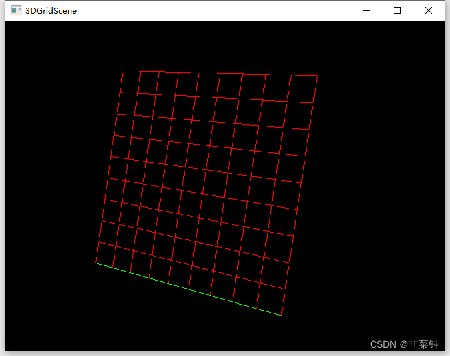
3.画个网格
参考这篇文章【OpenInventor实现场景索引线集管理之SoIndexedLineSet】,弄了个绘制网格的例子:
#include "mainwindow.h"#include <QApplication>
#include <QDebug>#include <Inventor/nodes/SoBaseColor.h>
#include <Inventor/nodes/SoCone.h>
#include <Inventor/nodes/SoSeparator.h>
#include <Inventor/VRMLnodes/SoVRMLGroup.h>#include <Inventor/nodes/SoPointSet.h>
#include <Inventor/nodes/SoCoordinate3.h>
#include <Inventor/nodes/SoIndexedLineSet.h>
#include <Inventor/nodes/SoLineSet.h>#include <Inventor/nodes/SoMaterial.h>
#include <Inventor/nodes/SoMaterialBinding.h>
#include <Inventor/nodes/SoTransform.h>
#include <Inventor/nodes/SoMatrixTransform.h>#include <Quarter/Quarter.h>
#include <Quarter/QuarterWidget.h>#include <QtMath>using namespace SIM::Coin3D::Quarter;int main(int argc, char *argv[])
{QApplication a(argc, argv);// MainWindow w;// w.show();// Initializes Quarter library (and implicitly also the Coin and Qt// libraries).Quarter::init();// Make a dead simple scene graph by using the Coin library, only// containing a single yellow cone under the scene graph root.SoSeparator * root = new SoSeparator;root->ref();// 绘制网格{// 根节点SoSeparator * lineRoot = new SoSeparator();lineRoot->ref();// 线段集SoIndexedLineSet *iLineSet = new SoIndexedLineSet();int gridRows = 10;int gridCols = 10;// 存放点数据的结构SbVec3f *points = new SbVec3f[2 * (gridCols + gridCols)];// 填充横线for(int i = 0; i < gridRows; i++){points[i * 2].setValue(0, i, 0);points[i * 2 + 1].setValue(gridCols - 1, i, 0);}// 填充竖线for(int i = 0; i < gridCols; i++){points[gridRows * 2 + i * 2].setValue(i, 0, 0);points[gridRows * 2 + i * 2 + 1].setValue(i, gridRows - 1, 0);}// 坐标系SoCoordinate3 *coord = new SoCoordinate3();// 将各个点填充至坐标系中coord->point.setValues(0, 2 * (gridCols + gridCols), points);// 保存线的索引int32_t *nLineSets = new int32_t[3 * (gridCols + gridRows)];// 每条线需要三个索引:起点、终点、结束符for(int i = 0; i < (gridCols + gridRows); i++){nLineSets[3 * i] = i * 2;nLineSets[3 * i + 1] = i * 2 + 1;// SO_END_LINE_INDEX的值是-1,-1代表一条索引线结束!!!nLineSets[3 * i + 2] = SO_END_LINE_INDEX;}iLineSet->coordIndex.setValues(0, 3 * (gridCols + gridRows), nLineSets);// 默认颜色为绿色,被选中的红色显示SbColor *color = new SbColor[2];color[0].setValue(1,0,0);color[1].setValue(0,1,0);SoMaterial *mat = new SoMaterial();mat->diffuseColor.setValues(0, 2, color);SoMaterialBinding *mb = new SoMaterialBinding;// 索引绑定材质!!!mb->value = SoMaterialBinding::PER_PART_INDEXED;// mb->value = SoMaterialBinding::PER_PART;// mb->value = SoMaterialBinding::OVERALL;// 设置线段的颜色for(int i = 0; i < (gridCols + gridRows); i++){// 这里的索引.第一个参数指的是第条线,第二个参数指的是mat->diffuseColor中的第几种材质iLineSet->materialIndex.set1Value(i, 0); // 第i个线段的颜色/}iLineSet->materialIndex.set1Value(0, 1); // 第i个线段的颜色/// 整体变换SbMatrix sbMatrix, tmpMat, tmpMat1;sbMatrix.makeIdentity(); // 变成单位矩阵// 平移、旋转、缩放需要单独进行,然后相乘tmpMat.makeIdentity();// tmpMat.setTranslate(SbVec3f(1, 0, 0));tmpMat.setRotate(SbRotation(SbVec3f(1, 0, 0), qDegreesToRadians(90.0)));tmpMat1.makeIdentity();tmpMat1.setScale(0.1);sbMatrix = tmpMat1 * tmpMat; // 越在右边的矩阵,逻辑上是越先被使用的SoMatrixTransform *matrix = new SoMatrixTransform;// matrix->matrix.setValue(sbMatrix);lineRoot->addChild(matrix);lineRoot->addChild(coord); // 组成线的点lineRoot->addChild(mat); // 线的材质lineRoot->addChild(mb); // 绑定材质lineRoot->addChild(iLineSet); // 线root->addChild(lineRoot);}// Create a QuarterWidget for displaying a Coin scene graphQuarterWidget * viewer = new QuarterWidget;viewer->setSceneGraph(root);viewer->viewAll();// make the viewer react to input events similar to the good old// ExaminerViewerviewer->setNavigationModeFile(QUrl("coin:///scxml/navigation/examiner.xml"));// viewer->setNavigationModeFile(QUrl("coin:///scxml/navigation/common.xml"));viewer->resize(640, 480);// Pop up the QuarterWidgetviewer->show();// return a.exec();a.exec();// Clean up resources.root->unref();delete viewer;Quarter::clean();return a.exec();
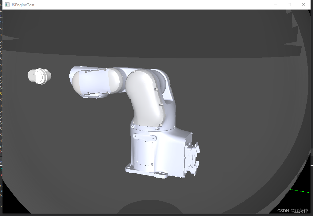
}4.加载wrl模型
参考【FengJungle /QtCoin3D_Robot 】,可以加载自己的wrl模型
// 加载模型SoVRMLGroup *model = nullptr;{SoInput * myInput = new SoInput;if(myInput->openFile("lr4-r560.wrl")){model = SoDB::readAllVRML(myInput);myInput->closeFile();delete myInput;}else{myInput->closeFile();delete myInput;}}if(model != nullptr){qDebug() << "num of children:" << model->getNumChildren();root->addChild(model);}
5.画个锤子并旋转
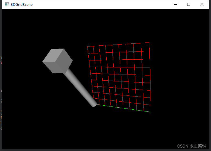
// 绘制锤子{// 创建一个组合节点,作为锤子的根节点SoSeparator* hammerRoot = new SoSeparator;// 创建一个旋转节点,用于绕圆柱体的末端旋转锤子SoRotation* rotation = new SoRotation;rotation->rotation.setValue(SbVec3f(1, 0, 0), M_PI * 0);// 将旋转节点添加到组合节点中hammerRoot->addChild(rotation);QSlider *slider = new QSlider(Qt::Horizontal);slider->resize(300, 20);QObject::connect(slider, &QSlider::valueChanged, [=](){rotation->rotation.setValue(SbVec3f(1, 0, 0), M_PI * ((double)slider->value()) / 100.0); // 绕Z轴旋转45度});slider->show();// 将手柄的位置调整一下,使得旋转中心在手柄末端SoTranslation* handleTranslation = new SoTranslation;handleTranslation->translation.setValue(0, 5, 0);hammerRoot->addChild(handleTranslation);// 创建圆柱体节点,作为锤子的手柄SoCylinder* handle = new SoCylinder;handle->radius = 0.5;handle->height = 10;hammerRoot->addChild(handle);// 将长方体放置在圆柱体的末端SoTranslation* headTranslation = new SoTranslation;headTranslation->translation.setValue(0, 5, 0);hammerRoot->addChild(headTranslation);// 创建长方体节点,作为锤子的头部SoCube* head = new SoCube;head->width = 2;head->height = 2;head->depth = 2;hammerRoot->addChild(head);root->addChild(hammerRoot);}
6.加载自定义视口文件
QString exePath = QDir::currentPath();QString filePath = QString("file:///%1/examiner.xml").arg(exePath);viewer->setNavigationModeFile(QUrl(filePath));
更加具体的其他操作还得研究研究。
参考:
【OpenInventor官方文档】
【coin3d】
【FengJungle /QtCoin3D_Robot 】
【OpenInventor实现场景索引线集管理之SoIndexedLineSet】


进行3d绘图 "Qt利用Coin3D(OpenInventor)进行3d绘图")


